Are you facing challenges in your construction project? Are you unsure about the technical aspects of mechanical, electrical, and plumbing
Introduction
A photometric plan demonstrates the lighting level overview of a certain area. It determines the lumen power and light output for the fixtures you’re installing in photometric design.
Unfortunately, if you don’t know how to read the lighting plan, it will not benefit you in any way. One thing that makes this plan appear difficult to read is that it has several data points. It may even look like a bunch of intricate statics and figures. Don’t let all this stuff fool you though! Reading a photometric plan is not as difficult as most people think!
This article will tell you everything you need to know about reading a photometric plan. So, let’s get started!
To study a photometric plan like a pro, there are certain terms you need to be familiar with. Some of those terms are;
Note, foot-candle is the most commonly used unit by photometric plan designers. They use it to determine light levels in outdoor spaces and businesses. It’s the recommended unit for calculating lighting levels by the IES. IES stands for the Illuminating Engineering Standards.
The photometric analysis consists of about 5 to 20 PDF pages with graphs and charts. During the preparation of the report, IES guidelines must be adhered to. The report will depend on the accuracy of the information provided during the study. However, the final application can differ from the provided results.
That said, a photometric report contains the following elements;
Now that you know what to expect in a photometric plan, let’s see how you can read and interpret it!
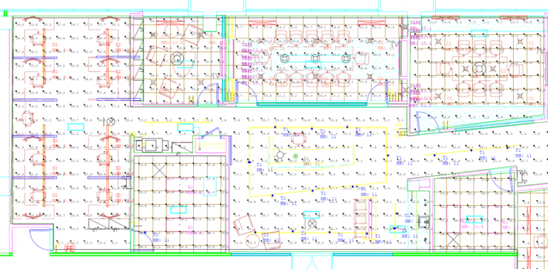
As you can see, a photometric plan contains a lot of data points. Uniformity and the average Fc (foot-candles) are the most important aspects to read. Meeting uniformity and your foot-candle goals is the top priority for photometric plan designers. With that in mind, here is how you read a photometric plan, starting with the site plan!
In most cases, the 1st page of a photometric plan is a site plan. This plan enables you to see the entire project. The site plan shows the following components;
The first thing you need is to look for symbols and shapes in a bright color on the site plan. In some instances, there are numbers or letters next to the symbols. This makes it easy for you to determine the type of proposed fixtures as per the lighting schedule.
Note, light fixtures are usually displayed as red dots. Designers position fixtures on areas that they’ll produce the optimal lighting coverage. They can swap out the fixtures and recalculate the plans. This helps them to find the perfect lighting for a specific area.
This shows the number of foot candles a certain point on the site plan has. The contour view arranges points with the same Fc rating together. This makes the calculation points easier to read. If you wish to see the details of the whole calculation zone, head to the calculation zone.
This is one of the most important sections of the photometric analysis. Thanks to the valuable information and statistics it contains. You can find this section on the right side of the schedule. It identifies the distribution ratios as well as light levels of the listed fixtures. A lighting plan has to comply with the city codes. To determine that, each calculation zone’s statistics have to be shown.
The calculation zone has some useful data about the Fc measurements on the plan. This includes;
Out of these statistics, the average Fc is the most important rating. It’s the ideal foot-candle rating for the whole project.
The schedule is often overlooked, yet it’s an important part of the lighting plan. You can find it at the bottom left side of the photometric plan. A lighting schedule highlights all the fixtures used on the project. Also, it goes further to give more details about each type of recommended fixture. This allows you to identify the fixture you’ll buy before construction begins.
Luminaire location schedule is another type of schedule included in the lighting plan. With this schedule, you can see the direction and location of each lighting fixture. Moreover, it enables contractors to view the recommended angle for installing the fixtures.
A photometric plan also contains a shaded view. By interpreting the shaded view as a heat map, you can easily view the site’s light levels. Bright reds indicate brighter levels, while dark blues indicate less bright levels.
By looking at the shaded view, photometric plan designers can identify the dark spots and hot spots. They use that information to change the plan to ensure uniform light distribution.
Unlike the shaded view, you can identify calculation points on the wireframe view. It’s the standard view when designers are creating a lighting plan. Apart from calculation points, this view contains contours as well. This enables readers to see the Fc ratings in a visual way. A ¾ wireframe frame enables you to see how the fixtures and the surface beneath interact.
Conclusion
If you’re in the lighting industry, you must know how to read a photometric plan. It will help you to properly measure and analyze the property lighting. Hopefully, after reading this article, you can now read any lighting plan effectively. But if you still have any questions or concerns, contact Innodez Design and Engineers. Our lighting specialists will be glad to help!
Introduction Most builders only focus on windows, roofs, and other openings to prevent water from getting into the home. But
About Author
InnoDez