Successful MEP Projects
Years in the Industry
Commercial and Industrial Projects
Weeks to Complete MEP Projects
MEP Engineering Service is an essential part of the building design process that aims to provide a safe and workable habitat for the owners and residents. “Mechanical” involves heating, cooling, and ventilation. The “Electrical” includes the power supply grid such as outlets and lighting fixtures of the structure, while the “Plumbing” is focused on water delivery and drainage of wastewater. MEP design should always be developed with the utmost accuracy and attention to detail.
We work as a unified team with dedicated professionals handling your project to ensure its successful completion. Our quality MEP design services can help you save time and money during the permit phase. A proper MEP design can result in fewer plan checks, comments, or revisions required by the city.


As the leading MEP design company in California, we take pride in providing quality design services to our clients. Our expertise lies in the field of MEP engineering, which encompasses Mechanical, Electrical, and Plumbing systems.
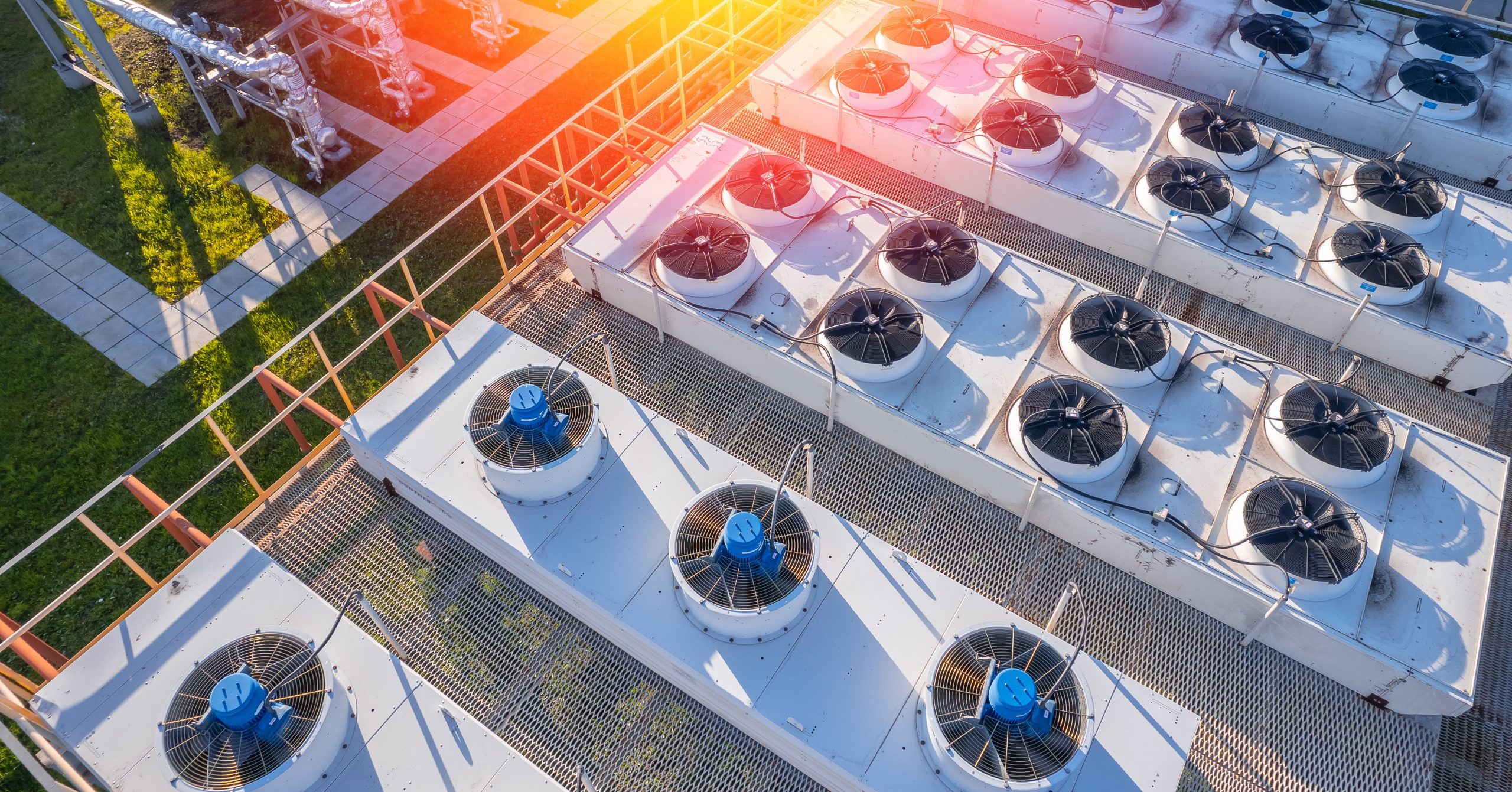
 When it comes to the mechanical aspect of a building, we specialize in designing heating, cooling, and ventilation systems that ensure optimal indoor comfort. Whether it’s a residential, commercial, or industrial project, our team of experienced engineers can tailor the mechanical systems to meet the specific requirements of the structure and its occupants. From energy-efficient heating systems to state-of-the-art air conditioning units, we strive to create designs that not only provide comfort but also promote sustainability.
 Our adept team specializes in meticulously tailoring efficient and reliable power systems for a diverse range of projects—residential, commercial, and industrial alike. Beyond the intricate web of wires, we orchestrate seamless power distribution and artful lighting solutions. Picture energy-efficient LED illumination bathing workspaces, corridors, and common areas, creating an ambiance that inspires productivity. Imagine robust electrical panels seamlessly managing power flow, safeguarding against disruptions. From blueprint to approval, excellence empowers your spaces.
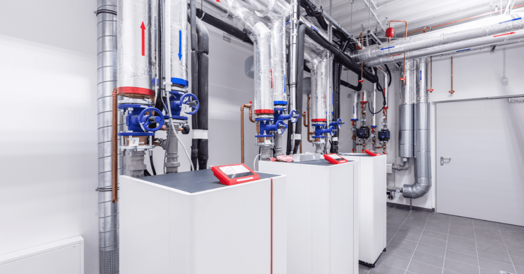
 Plumbing is another crucial aspect of building design, as it focuses on water delivery and wastewater drainage. Our MEP design services include comprehensive plumbing designs that ensure efficient water distribution and disposal systems. From designing water supply networks to sewage disposal systems, our team of plumbing engineers has the expertise to create designs that meet all regulatory requirements and provide convenience for the building occupants.
Our mechanical engineers are composed of experienced designers working to provide cost-effective and flexible solutions to even the most complicated projects. The HVAC system is a key mechanical component of every project. The implementation of a correct HVAC system will ensure that the building maintains an adequate temperature and humidity level throughout its occupancy, and ultimately offer maximal comfort to all its users.
At InnoDez we are proud to have some of the most well-versed specialists that ensure our HVAC systems and other MEP design services are always compliant with building codes. Our MEP designs also ensure quick and pain-free city approval.
Our mechanical engineering services include:
• Heating design
• Cooling design
• Humidifying design
• Dehumidifying design
• Cleaning: removing particulates and contaminants
• Ventilation: diluting gaseous pollutants
• Air movement and air treatment system design: circulating and mixing air for proper ventilation and thermal energy transfer
• Humidification Control
• Radiant hydronic system
• Geothermal Heat Transfer
• Smoke Management System


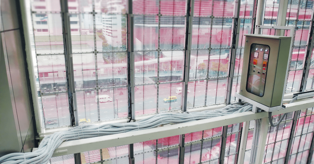
Electrical engineering is another key element of our MEP services here at InnoDez.
It includes lighting, receptacles, mechanical power, electrical riser diagrams,
panel board schedules, specifications, and construction details from low to high voltage
building systems, normal and emergency power.
Our electrical designers can specify an
installation that delivers the power required by your building while operating safely
and meeting the applicable building codes.
• Design Basis requirements and Electrical Load calculations
• Lighting layout and Lighting calculations
• Cable sizing calculation
• Single Line Diagrams (SLDs)
• Lightning protection calculation and Lightning protection layout
• Power and Small Power Distribution Layout
• Security Systems Layout
• Building & Energy Management and Control System Design
• Emergency, UPS, and Standby Power Design
• Photometric Study for Indoor & Outdoor Lighting
• Data and Telecom Design
At InnoDez, our MEP services extend beyond mechanical and electrical design to encompass critical plumbing engineering. Whether it’s a residential haven, a bustling commercial space, or an industrial facility, our skilled team tailors systems to meet specific needs.
From water supply and drainage to sanitation systems, we leave no faucet unturned.
Our InnoDez specialists can deliver quick schedules and final submissions, thus ensuring that the design is completed in due time, while still complying with all local codes and project requirements.
• Hot & Cold-water capacity calculations
• Sizing & Selection of Calorifiers, Pumps
• Water Storage Tanks
• Pipe sizing for water services
• Water Services Schematics
• Vacuum Piping Design
• Fuel Gas Piping Design
• Compressed Air Systems
• Medical and Laboratory Gases
• Hydraulic Fluids
• Industrial Waste Collection
• Pools and Fountains
• Water Treatment Filtration and DI Water Systems


At InnoDez, we specialize in two critical aspects of fire protection engineering:
Fire Sprinkler System Design: Our experts meticulously create robust fire sprinkler systems. These systems play a vital role in safeguarding lives and property. Compliance with regulations is our priority.
Fire Alarm System Design: Beyond sprinklers, we design comprehensive fire alarm systems. These systems provide early detection, alerting occupants to evacuate swiftly. From commercial spaces to residential buildings, our designs ensure safety and peace of mind.
• Design of Fire Sprinkler system as per NFPA 13 and local AHJ requirements.
• Hydraulic Calculation based on NFPA-13/13R/13D as required.
• Selection of sprinkler heads, and fire pumps if required.
• Water Spray Fixed Systems for Fire Protection
• Foam-Water Sprinkler and Foam-Water Spray Systems
• Fire Suppression System including NOVEC & FM-200
• Fire Alarm System Design
At InnoDez, we specialize in ensuring that your buildings meet energy efficiency standards and comply with regulations. Our energy compliance services encompass a range of critical aspects:
Energy Code Compliance: We meticulously analyze local and national energy codes to ensure your project aligns with the latest requirements. From insulation levels to lighting efficiency, we leave no stone unturned.
Performance Modeling: Our experts use advanced modeling tools to predict energy consumption, assess daylighting, and optimize HVAC systems. This data-driven approach informs design decisions, leading to sustainable and cost-effective solutions.
Renewable Energy Integration: Whether it’s solar panels, geothermal systems, or wind turbines, we explore renewable energy options to reduce your building’s carbon footprint. Our designs seamlessly integrate these technologies.
In California, Title 24 California Building Standards Code is a broad set of requirements
for “energy conservation, green design, construction and maintenance, fire and life safety, and accessibility” that apply to the “structural, mechanical, electrical, and plumbing systems” of a building.
• REScheck
• COMcheck
• Title 24 Energy Calculations Reports
• Energy Gauge
• Other State-Specific Reports

Our service area extends far beyond California, reaching clients across multiple states. Whether you’re in Los Angeles, San Francisco, San Diego, Miami, Atlanta, Orlando, Dallas, Houston, Philadelphia, or any other vibrant city, we are dedicated to providing exceptional MEP design services tailored to your specific needs.
Versatility Across Project Sizes: No project is too small or too large for us. From cozy residential ventures to sprawling industrial complexes, our team of skilled engineers adapts seamlessly to any project size. We understand that each endeavor is unique, requiring a customized approach. That’s why we collaborate closely with our clients, diving deep into their goals and requirements.
Our Commitment: With years of experience and a multi-state presence, we bring innovation, expertise, and professionalism to every project. Whether it’s optimizing energy efficiency, ensuring compliance with regulations, or creating sustainable designs, we’re here to elevate your vision. Let’s build together!


Heating design is a crucial aspect of building construction and infrastructure development. It involves the planning and implementation of heating systems within a building to ensure comfortable and efficient thermal conditions. The goal of heating design is to create a balanced and sustainable heating system that meets the specific requirements of the building occupants while minimizing energy consumption and environmental impact.
The first step in heating design is to assess the heating needs of the building. Factors such as the size and layout of the space, the climate conditions in the region, and the occupancy patterns are taken into consideration. This information is used to determine the heating load, which is the amount of heat required to maintain a desired indoor temperature.
Once the heating load is calculated, the next step is to select appropriate heating equipment and design a distribution system. This includes choosing the right type of heating system, such as boilers, furnaces, or heat pumps, and determining the capacity and efficiency of these systems. The distribution system involves designing the layout of pipes, ducts, vents, and radiators to ensure even heat distribution throughout the building.
In addition to selecting and designing the heating equipment and distribution system, heating design also involves integrating control systems and automation. These systems allow for precise temperature control, scheduling, and energy management. They can be programmed to adjust heating levels based on occupancy patterns or time of day, thereby optimizing energy efficiency.
Overall, heating design plays a crucial role in creating comfortable and energy-efficient indoor environments. By carefully considering the heating needs of a building and implementing appropriate systems and controls, MEP engineers can ensure that occupants are provided with a comfortable thermal environment while minimizing energy consumption and environmental impact.
Cooling design is an integral part of any building’s mechanical, electrical, and plumbing systems. It involves the planning and implementation of a comprehensive cooling system that ensures the comfort and safety of the building occupants. The design process typically includes evaluating the cooling load requirements, selecting the appropriate equipment, and creating an efficient distribution system.
One key aspect of cooling design is determining the cooling load of the building. This involves calculating the amount of heat that needs to be removed from the space to maintain a comfortable indoor temperature. Factors such as the building’s size, orientation, insulation, and occupancy levels are taken into consideration to accurately determine the cooling load.
Once the cooling load is determined, selecting the appropriate equipment is crucial. This includes choosing the right type and capacity of chillers, air handling units, fans, and pumps. Energy efficiency is an important consideration during this stage, as it helps reduce operating costs and minimize environmental impact.
Creating an efficient distribution system is also essential in cooling design. This involves designing ductwork or piping layouts that ensure proper airflow and temperature control throughout the building. The placement of vents or diffusers, as well as the sizing of ducts or pipes, are carefully planned to optimize cooling performance.
In conclusion, cooling design plays a critical role in creating comfortable and energy-efficient buildings. It involves calculating the cooling load, selecting appropriate equipment, and designing an efficient distribution system. By considering these factors, MEP engineers can create cooling systems that meet the needs of building occupants while minimizing energy consumption and operating costs.
Humidifying design refers to the process of designing and implementing systems that add moisture to indoor spaces in order to maintain optimal humidity levels. This is a crucial aspect of building design and HVAC systems, as proper humidity control is essential for the comfort and well-being of occupants, as well as for the preservation of materials and equipment.
In humidifying design, various factors need to be considered. These include the size and layout of the space, the desired humidity levels, the type of HVAC system in place, and the specific needs of the occupants. The design process involves selecting the appropriate humidification equipment, such as steam humidifiers or evaporative humidifiers, and determining their placement within the building.
The goal of humidifying design is to create a balanced and controlled humidity environment that meets the needs of the occupants while minimizing energy consumption. This requires careful calculations and considerations to ensure that the humidification system is properly sized and integrated with other MEP systems.
Proper humidifying design can have numerous benefits. It can improve indoor air quality, reduce respiratory problems, alleviate dry skin and irritation, and prevent damage to furniture, artwork, and sensitive equipment. Moreover, it can enhance occupant comfort and productivity, particularly in spaces where precise humidity control is necessary, such as laboratories or healthcare facilities.
In conclusion, humidifying design plays a vital role in creating comfortable and healthy indoor environments. It requires meticulous planning and expertise to ensure that the systems are properly designed, installed, and maintained. By considering various factors and integrating humidification systems with other MEP components, designers can create spaces that promote well-being and efficiency.
When it comes to dehumidifying design, careful consideration must be given to various factors in order to create an efficient and effective system. Dehumidification is the process of removing excess moisture from the air, which is essential for maintaining a comfortable and healthy indoor environment. In MEP design, this involves the selection and sizing of appropriate equipment, such as dehumidifiers, as well as the integration of these systems into the overall building design.
One important aspect of dehumidifying design is determining the moisture load within the space. This involves calculating the amount of moisture generated by occupants, equipment, and other sources. By accurately estimating the moisture load, engineers can select dehumidifiers with the appropriate capacity to effectively remove moisture from the air. Additionally, proper ventilation and airflow management must be considered to ensure that the dehumidification system can efficiently distribute dry air throughout the space.
Another key consideration in dehumidifying design is energy efficiency. Dehumidification systems can consume a significant amount of energy, so it is important to select equipment that is energy efficient and properly sized for space. Additionally, incorporating energy recovery systems, such as heat exchangers, can help reduce the overall energy consumption of the system by utilizing waste heat to pre-condition incoming air.
Overall, dehumidifying design requires a thorough understanding of the space’s moisture load and careful selection of equipment to ensure effective moisture removal. By considering factors such as ventilation, airflow management, and energy efficiency, engineers can create a dehumidification system that provides a comfortable and healthy indoor environment while minimizing energy consumption.
A ventilation system plays a crucial role in diluting gaseous pollutants and maintaining indoor air quality. Gaseous pollutants, such as volatile organic compounds (VOCs), carbon monoxide, and nitrogen dioxide, can be harmful to human health if present in high concentrations. These pollutants are released from various sources, including building materials, cleaning products, and combustion processes. The ventilation system helps to remove these pollutants by introducing fresh outdoor air and exhausting stale indoor air.
One method used by a MEP ventilation system to dilute gaseous pollutants is using mechanical fans. These fans create airflow within the building, allowing for the exchange of indoor and outdoor air. By continuously circulating the air, the system helps to reduce the concentration of gaseous pollutants and maintain a healthy indoor environment. Additionally, the ventilation system can incorporate filters that remove particulate matter and certain gases, further improving air quality.
Proper design and installation of a ventilation system are essential to ensure effective dilution of gaseous pollutants. Factors such as the size of the building, occupancy levels, and pollutant sources need to be considered when determining the ventilation requirements. Additionally, regular maintenance and inspections are necessary to ensure that the system is functioning correctly and providing adequate ventilation.
In conclusion, a ventilation system is an integral part of any building’s infrastructure for diluting gaseous pollutants. By introducing fresh outdoor air and removing stale indoor air, the system helps to maintain a healthy indoor environment by reducing the concentration of harmful gases. Proper design, installation, and maintenance are crucial for ensuring the effectiveness of the ventilation system in diluting gaseous pollutants and promoting indoor air quality.
MEP (Mechanical, Electrical, and Plumbing) air movement and air treatment system design play a crucial role in creating a comfortable and healthy indoor environment. The design of these systems involves various components and considerations to ensure optimal air quality, temperature control, and ventilation.
Air movement systems are responsible for circulating the air within a building. This includes the design of ductwork, fans, and other equipment that helps to distribute conditioned air throughout the space. Proper airflow is essential for maintaining a comfortable temperature, removing odors, and preventing the buildup of pollutants. The design of these systems takes into account factors such as the size and layout of the building, the number of occupants, and the specific requirements of each space.
Air treatment systems focus on improving the quality of the air by removing contaminants and controlling humidity levels. These systems may include filters, humidifiers, dehumidifiers, and other equipment to ensure that the air is clean and healthy. The design of air treatment systems considers factors such as the desired level of filtration, the type of pollutants present in the environment, and the specific needs of the occupants.
Overall, air movement and air treatment system design is essential for creating a comfortable and healthy indoor environment. By considering factors such as airflow, temperature control, and air quality, these systems can help to improve occupant comfort and well-being. Additionally, proper design can also lead to energy efficiency and cost savings by optimizing the performance of HVAC equipment.
Electrical engineering is another key element of our MEP services here at InnoDez.
It includes lighting, receptacles, mechanical power, electrical riser diagrams,
panel board schedules, specifications, and construction details from low to high voltage
building systems, normal and emergency power.
We offer electrical design services for all types of buildings.
A well-designed electrical system is a cornerstone for many other building systems,
including air handlers, water pumps, air conditioners, communication networks,
lighting, and office equipment. Our electrical designers can specify an
installation that delivers the power required by your building while operating safely
and meeting the applicable building codes.
Our advanced Energy Modelling software allows us to accurately estimate the total energy usage of the structure and generate a breakdown of the energy requirement for each electrical component in the building. We also aim to integrate alternative energy sources like solar panels, natural gas generators, co-generators, micro-turbines, and diesel generators to every project where they prove to be efficient and cost-effective.
The electrical design basis requirements and electrical load calculations are crucial aspects of any building design. These requirements set the foundation for the design and installation of the MEP systems, ensuring that they meet the needs of the building occupants while adhering to safety standards and regulations. The design basis requirements include factors such as the building’s purpose, occupancy, size, and location, which help determine the specific needs of the MEP systems.
Electrical load calculations are an essential part of the MEP design process, as they determine the amount of electrical power required for a building. These calculations consider various factors such as lighting, heating, ventilation, air conditioning, and other electrical equipment that will be installed in the building. By accurately calculating the electrical load, designers can ensure that the electrical system is properly sized to handle the expected demand.
To perform electrical load calculations, designers consider the wattage or power consumption of each electrical component and sum them up to determine the total load. This helps determine the size of equipment such as transformers, switchgear, and distribution panels needed to handle the load. Additionally, load calculations also consider factors such as diversity and demand factors, which account for variations in usage patterns and reduce the risk of overloading the electrical system.
Overall, electrical design basis requirements and electrical load calculations are essential components of building design. They ensure that the MEP systems are designed to meet the specific needs of a building while adhering to safety standards and regulations. Accurate load calculations help prevent electrical system failures and ensure efficient and reliable operation of electrical equipment within a building.
Lighting layout and lighting calculations are crucial aspects of any building design. Proper lighting is essential for creating a functional and aesthetically pleasing environment. The electrical engineer is responsible for designing the lighting layout, which includes determining the placement and type of light fixtures throughout the building.
The lighting layout takes into consideration various factors such as the purpose of each space, the activities that will be performed in each area, and the desired ambiance. The electrical engineer carefully analyzes these factors to determine the appropriate number and type of light fixtures needed in each space. They also consider factors such as energy efficiency and sustainability when selecting light fixtures.
Lighting calculations are an integral part of the lighting design process. These calculations involve determining the lighting levels required in each area of the building. The electrical engineer considers industry standards and guidelines to ensure that the lighting levels meet the specific requirements of each space. Factors such as the type of activity, the size of the space, and the height of the ceiling are taken into account during these calculations.
Accurate lighting calculations are essential for providing a comfortable and safe environment. Insufficient lighting can lead to eye strain and discomfort, while excessive lighting can cause glare and waste energy. Therefore, electrical engineers use specialized software to perform lighting calculations and simulations to ensure optimal lighting conditions in every area of the building.
In conclusion, lighting layout and lighting calculations are critical components of building design. The electrical engineer carefully plans the placement and selection of light fixtures based on factors such as space usage and desired ambiance. Lighting calculations help determine the appropriate lighting levels for each area, ensuring a comfortable and safe environment for occupants.
Cable sizing calculation is an essential aspect of any construction or renovation project. It involves determining the appropriate size of cables to ensure efficient and safe electrical distribution within a building. Cable sizing calculations consider factors such as the load, voltage drop, and ambient temperature to determine the optimal cable size. This is crucial to prevent overheating, voltage fluctuations, and electrical hazards. By accurately calculating cable sizes, professionals in the MEP industry can ensure that electrical systems function optimally and meet the required safety standards.
Single Line Diagrams (SLDs) are an essential tool used in electrical engineering and power systems analysis. These diagrams provide a simplified representation of the electrical system, showing the flow of electrical power from the generation source to the various loads. SLDs are commonly used in the design, operation, and maintenance of electrical systems.
The main purpose of an SLD is to provide a clear and concise visual representation of the electrical system. It shows the major components of the system, such as generators, transformers, circuit breakers, and loads, along with the interconnections between them. By using standardized symbols and labels, SLDs make it easier for engineers, technicians, and operators to understand and communicate about the system.
SLDs are particularly useful in troubleshooting and fault analysis. When an electrical problem occurs, engineers can refer to the SLD to quickly identify the affected components and determine the possible causes of the fault. This saves time and effort in locating and rectifying the issue.
Furthermore, SLDs play a crucial role in system planning and design. Engineers use these diagrams to evaluate the capacity and performance of the electrical system. They can identify potential bottlenecks or areas of improvement and make informed decisions about system upgrades or expansions.
In conclusion, Single Line Diagrams (SLDs) are a valuable tool in electrical engineering. They provide a simplified representation of electrical systems, aiding in design, operation, troubleshooting, and planning. SLDs enhance communication and understanding among engineers, technicians, and operators, ensuring the efficient and reliable operation of electrical systems.
Lightning protection calculation and lightning protection layout are crucial aspects of ensuring the safety of a building and its occupants. Lightning strikes can cause severe damage to structures and pose a significant risk to human life. Therefore, it is essential to design and implement an effective lightning protection system.
The first step in lightning protection calculation is to assess the building’s risk of being struck by lightning. This involves considering factors such as the building’s height, geographical location, and the presence of tall objects nearby that could attract lightning. By conducting a thorough risk assessment, engineers can determine the level of protection needed for the building.
Once the risk assessment is complete, engineers can proceed with the lightning protection layout. This involves determining the placement of lightning rods, conductors, and grounding systems. Lightning rods are installed at strategic locations on the building’s roof to intercept the lightning strike and safely conduct it to the ground. Conductors are used to connect the lightning rods to the grounding system, which disperses the electrical charge harmlessly into the earth.
The layout of a lightning protection system should comply with relevant industry standards and regulations. These standards provide guidelines on factors such as the minimum number of lightning rods required, conductor sizing, and grounding system design. Adhering to these standards ensures that the lightning protection system is effective and reliable.
In conclusion, lightning protection calculation and lightning protection layout are critical components of building safety. By conducting a thorough risk assessment and designing an appropriate lightning protection system, engineers can minimize the risk of damage and injury caused by lightning strikes. It is essential to follow industry standards and regulations to ensure an effective and reliable lightning protection system.
Power and small power distribution layout is a crucial aspect of any building design. The power distribution layout specifically focuses on the electrical systems, ensuring that electricity is distributed efficiently and safely throughout the building.
When designing power and small power distribution layouts, several factors need to be considered. These include the electrical load requirements of the building, the location of electrical equipment, the routing of electrical cables, and compliance with safety codes and regulations. Additionally, the layout must also consider future expansion or modifications that may be needed.
The small power distribution layout involves the design and placement of electrical outlets, switches, and other power points throughout the building. These small power outlets provide electricity for various equipment and appliances in different areas of the building. It is essential to carefully plan the placement of these outlets to ensure that they are easily accessible and meet the needs of the occupants.
Overall, power and small power distribution layout play a significant role in the functionality and efficiency of a building. By carefully planning and designing these systems, engineers can ensure that electricity is distributed safely and effectively, meeting the power needs of the building’s occupants. This layout also allows for flexibility and adaptability as the building’s requirements change over time.
A photometric plan is a crucial aspect of any building design and construction project. It involves the detailed layout of lighting fixtures and their positioning to ensure optimal illumination in various areas of the building. The purpose of the photometric plan is to determine the lighting levels required for different spaces, such as offices, conference rooms, lobbies, and parking lots. This plan considers factors like the type of lighting fixtures, their wattage, and the specific requirements of each area. By carefully designing the lighting layout, the photometric plan contributes to energy efficiency, occupant comfort, and overall aesthetics of the building. It is an essential part of the MEP (Mechanical, Electrical, and Plumbing) coordination process, ensuring that lighting systems are integrated seamlessly with other building systems.
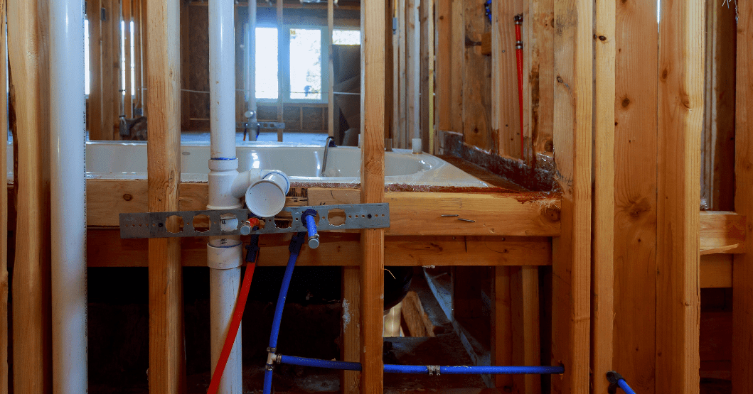
When it comes to plumbing design, one crucial aspect is calculating the hot and cold-water capacity. This calculation helps determine the necessary amount of water supply in a building, ensuring that there is enough hot and cold water for all the occupants’ needs. The hot water capacity calculation considers various factors such as the number of fixtures, the flow rate of each fixture, and the peak demand. By considering these factors, engineers can accurately determine the required size of the water heating system and avoid any issues related to inadequate hot water supply.
Similarly, the cold-water capacity calculation is essential to ensure that there is sufficient water supply for various purposes like drinking, washing, and irrigation. This calculation involves considering factors such as the number of occupants, the flow rate of fixtures, and any specific requirements for specialized equipment or processes. By accurately calculating the cold-water capacity, engineers can design a plumbing system that meets the building’s demands without any shortages or disruptions.
Overall, hot and cold-water capacity calculations are crucial for designing efficient plumbing systems in buildings. These calculations help determine the appropriate size of water heating systems and ensure there is enough hot water available for all occupants’ needs. Additionally, accurately calculating the cold-water capacity helps ensure a reliable water supply for various purposes. By considering these calculations during the design phase, engineers can create plumbing systems that meet the building’s requirements while also ensuring user comfort and satisfaction.
Sizing and selection of calorifiers and pumps is a critical aspect of designing an efficient and reliable heating system. Calorifiers, also known as hot water storage tanks, play a vital role in storing and supplying hot water for various applications in buildings. The sizing of calorifiers depends on factors such as the building’s hot water demand, peak flow rate, and storage capacity requirements. Proper sizing ensures that the calorifier can meet the hot water demand without running out of supply or causing excessive energy losses.
Similarly, pumps are essential components in heating systems as they circulate hot water or other fluids throughout the system. The selection of pumps involves considering factors like flow rate, head pressure, efficiency, and system design parameters. Pumps need to be sized correctly to ensure proper circulation and avoid issues such as insufficient flow or excessive pressure drops.
Both calorifiers and pumps must be selected based on the specific requirements of the building and the heating system design. This involves evaluating factors such as the number of occupants, usage patterns, building size, and desired comfort levels. Additionally, considerations like energy efficiency, maintenance requirements, and cost-effectiveness should also be taken into account during the sizing and selection process.
Overall, sizing and selection of calorifiers and pumps requires a thorough understanding of the building’s hot water demand and heating system design. By ensuring proper sizing and selection, engineers can design efficient and reliable heating systems that meet the occupants’ needs while minimizing energy consumption and operating costs.
Water storage tanks play a crucial role in ensuring a reliable and efficient water supply system. These tanks are designed to store water for various purposes, such as domestic use, irrigation, fire protection, and industrial applications. They are typically made of durable materials like concrete or steel to withstand the weight of the stored water and external forces.
One of the main advantages of water storage tanks is their ability to store large volumes of water. This is especially important in areas where water scarcity is a concern or during times of drought. These tanks can hold thousands or even millions of gallons of water, providing a buffer during periods of low rainfall or high demand.
In addition to storing water, water storage tanks also help in maintaining water quality. By preventing direct exposure to sunlight and limiting contact with external contaminants, these tanks ensure that the stored water remains clean and safe for consumption. Proper maintenance and regular cleaning are essential to prevent the growth of bacteria or algae and preserve the quality of the stored water.
Furthermore, water storage tanks are designed with features to facilitate the efficient distribution of water. They are equipped with inlet and outlet pipes, valves, and pumps to regulate the flow of water in and out of the tank. Additionally, these tanks may be connected to a network of pipes and distribution systems to supply water to various locations.
Overall, water storage tanks are essential components of a well-designed water supply system. They provide a reliable source of water for various purposes while ensuring its quality and efficient distribution. Proper design, installation, and maintenance are key to maximizing the benefits of these tanks and ensuring a sustainable water supply for communities and industries.
When it comes to designing water services for a building, MEP engineers play a crucial role in determining the appropriate pipe sizing. Pipe sizing is essential to ensure that water is distributed efficiently and effectively throughout the building. It involves calculating the required flow rates and pressure drops for various fixtures and appliances.
To achieve proper pipe sizing, engineers consider several factors, including the type of building, the number of occupants, and the fixtures being used. They also consider the available water supply and the pressure requirements for each fixture. By analyzing these factors, engineers can determine the appropriate pipe size for each section of the water distribution system.
One of the main goals of pipe sizing in plumbing design is to minimize pressure drops. Pressure drops occur when water flows through pipes, fittings, and valves, causing a decrease in pressure. If the pipe size is too small, there will be a significant pressure drop, resulting in reduced water flow and inadequate performance of fixtures. On the other hand, oversized pipes can lead to higher construction costs and unnecessary energy consumption.
In addition to minimizing pressure drops, proper pipe sizing also ensures that water is delivered at the desired flow rates to each fixture. This is crucial for maintaining user comfort and meeting the demands of different appliances. By accurately sizing pipes, engineers can ensure that water services in a building operate efficiently and effectively, providing a reliable supply of water to occupants throughout the day.
Water services schematics play a crucial role in the design, installation, and maintenance of water systems in buildings. These schematics provide a detailed representation of the layout and configuration of the plumbing and water supply systems. They include information about the location of pipes, valves, pumps, and other components, as well as their sizes and connections. Water services schematics are essential for ensuring that the water distribution system functions efficiently and meets the requirements of the building occupants.
One of the primary benefits of water services schematics is that they allow for proper planning and coordination during the construction phase. By having a detailed representation of the water system, architects, engineers, and contractors can work together to ensure that all components are properly integrated into the building design. This helps to minimize errors, reduce rework, and improve overall project efficiency.
In addition to aiding in the construction process, water services schematics also serve as a valuable reference for ongoing maintenance and troubleshooting. By having a clear visual representation of the system, maintenance personnel can quickly identify and locate components, making repairs and replacements more efficient. This helps to minimize downtime and ensure that the water supply remains uninterrupted.
Overall, water services schematics are an integral part of any building project that involves water distribution systems. They provide a detailed representation of the system layout, aiding in planning, coordination, and maintenance. By utilizing these schematics, professionals can ensure that water services are designed and installed to meet the needs of the building occupants while adhering to industry standards and regulations.
Vacuum piping design is a crucial aspect of any building’s mechanical, electrical, and plumbing systems. Vacuum piping plays a vital role in various industries, including pharmaceuticals, laboratories, and manufacturing plants. The design process involves careful planning and consideration of factors such as the required vacuum levels, the type of equipment to be connected, and the layout of the building. The goal is to create an efficient and reliable vacuum system that meets the specific needs of the facility. This involves selecting the appropriate materials, sizing the pipes correctly, and ensuring proper installation to minimize leaks and maximize performance. A well-designed vacuum piping system can enhance productivity, improve safety, and reduce operational costs in a variety of applications.
Fuel gas piping design is a critical aspect of building infrastructure that requires careful planning and expertise. The design process involves determining the appropriate size and layout of the piping system to ensure efficient and safe delivery of fuel gas to various appliances and equipment. It is important to consider factors such as pressure drop, gas flow rate, and material compatibility when designing the piping system. Additionally, compliance with local codes and regulations is necessary to ensure the safety of occupants and prevent potential hazards. A well-designed fuel gas piping system can enhance the overall functionality and performance of a building while ensuring the safety of its occupants.


– One-stop Shop for all your design and engineering needs
– Simple and fast process to get started
– Quality that is affordable
– Teamwork with clients
– Fast and simple communications
– Responsible and responsive
– Ability to take on a project anytime
– Continuous and responsive communications
– Expert at codes and standards

"We have consulted with InnoDez Design and Engineering on various commercial and industrial projects for approximately 1-1/2 years now. They have provided mechanical, electrical, plumbing design and construction documents as well as Title 24 Energy Compliance documentation. Their staff is courteous, professional, and always respond in an expeditious manner. The"

"In searching for a qualified Engineering firm for our Architectural projects, we discovered InnoDez Engineering. They offer Mechanical, Electrical, Structural and Civil Engineering services. The most important parts of working with an Engineering firm are communication, qualifications and obtaining permits. InnoDez does all three. They provide a contact person who"

"InnoDez Engineering offers a wide range of architectural engineering services and is a well-organized highly reliable organization. Our office has a dozen new residential projects approved and under construction thanks to our association with InnoDez. They have become our go-to service for MEP design and Title 24 calculations, but also"